Note: This is an older design using a brushed motor and NiCd cells, but it would be the same design for brushless motors and Lipo cells. I also have an RCGroups Build Log of a similar brushless / Lipo plane.
I've found few things are as satisfying as making your own plane, a blend of science and art, letting your creative genius out, and watching it takeoff and fly well as a result of something you designed and made with your own hands.
The Plane
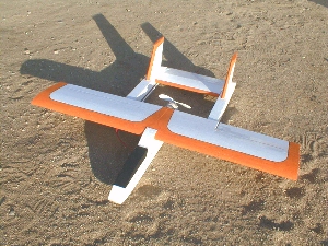
This article describes how to make a basic twin-boom foamie pusher for a Speed 400 motor. The wingspan is 36 inches. It's very typical of my excellent flying "So" series of planes, such as this So.11:
An advantage of this design is that when a 6" prop is used (as per these instructions), the prop will not hit the ground upon landing.
You will not find plans of this plane here. Since I don't draw plans I don't have any. But this design is so simple all that are needed are some basic drawings of the layout:
The Foam
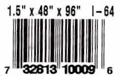
There are many types of foam, but this article will focus on the use of white EPS (Expanded PolyStyrene) foam. This foam is available in small or large sheets of various thicknesses from most Home Depots or Lowes. It has the brand name Premier Insulfoam and is normally used for wall insulation. It has a blue (used to be silver) plastic film on one side, and a white plastic film with blue lettering on the other. I usually use the 1-1/2-inch thickness (actually 1-3/8 inches). You can get 4 x 8-foot sheets, or 2 x 4-foot sheets. I usually buy the 2x4 sheets as they're easier to handle and transport, they cost about US$3.15 each. You don't save much money by buying the 4x8 sheets, less than US$1.
Here's the bar code from a sheet of foam. This may help you locate and purchase it:
Cutting Foam
There are many ways to cut the foam. This article is not about hot-wire cutting, but this method will give nice cuts, and there are other instances when a bandsaw or knife can be used. To cut a smaller piece out of a large sheet of foam, a handsaw can be used. I use a hacksaw blade with tape covering part of it to act as a handle. If using this method, cut around the part on the sheet, then finish cutting the part out with a bandsaw or hot wire. Using a handsaw to actually cut the foam parts can lead to more sanding and inaccuracies.
Cutting Parts
Draw the plane's parts onto the foam sheet before peeling the film off. This way you won't get ink on the foam. With a black sharpie and a ruler or yard stick, draw the parts of the plane onto the foam sheet. Then cut the parts out with a bandsaw. Peel the silver and white films, and sand all the surfaces. A sanding block with about 200-grit works well. Be very careful sanding, as it's easy to gouge the foam.
After sanding, it's a good idea to get all the foam dust off the parts. I use compressed air at 50-100 PSI for this. You could also vacuum the dust away, but if you do be careful to not gouge the foam with the vacuum hose or attachment.
Note that as indicated on the side view, the total fuselage length is about 20 inches, and the total boom lengths are about 20 inches. These don't have to be exact. Also, the vertical fins should be around 5 or 6 inches tall and can be almost whatever shape you want, again these dimensions don't have to be exact. I hot-wire the stabilizer and fins to a symmetrical airfoil shape, but you could also probably get away with having them flat foam, but flat foam would be weaker. Remember, the most important measurements on this plane are the CG location, and just ensuring the entire plane is aligned straight. The lengths of the fuselage, tail booms, stabilizer span and fin dimensions are not that critical.
Once all the parts are cut and sanded you have a "kit" in which to build!
Construction
There are many adhesives for foam, but I use hot-melt glue on the low-temperature setting. This of course requires a glue gun with a low-temp setting, and you should test on scrap pieces of foam first to be sure it adheres well, but without melting the foam. I use a Stanley GR25 Pro glue gun, dual temperature range, 40 watts.
Tape Spar
There are some important things to do before beginning assembly. The most important is to apply the strapping tape spar to the bottom of the wing. Cut a length of strapping tape the full span of the wing. Lay the strip of tape onto a surface with the adhesive side up. Use spray glue to coat the tape, as the tape itself is not sticky enough. Then apply the tape to the bottom of the wing from wingtip to wingtip, at about 1/3 back from the leading edge. Don't press the tape down too hard, because it will deform the foam. Just smooth it out to avoid wrinkles, start at the center and press it down towards each wingtip. Cut any excess tape that overhangs the wingtips. After this you may notice the strapping tape still slightly bowed the wing, but don't worry about it.
Control Surfaces
Next cut the elevator out of the stabilizer, and cut the aileron out of the wing. This is easier to do before assembly of the plane. The elevator and the aileron hinge points will need to be beveled at a 30-45-degree angle (this can be done on the bandsaw easily). Next insert the small balsa control horn mounting blocks into the elevator and aileron. I just use a knife to cut a square hole all the way through the foam, then hot-glue the block in well.
Hinging
Next attach the elevator to the stabilizer and the aileron to the wing with clear packing tape. It may take some practice to get it right, but the results are a strong hinge line, sealed with no gap. Apply a strip of packing tape the full length of the surface on both sides. Make sure the surface is at full deflection before applying the tape, or the surface will bind. Trim the tape at the ends of the surfaces, and cut away the small square of tape covering the top sides of the balsa control horn mounting blocks. Lastly, install the control horns to each balsa block.
Motor Mount
There are several ways to mount the motor, but here's what I do. It's important to get this part in the correct alignment. Cut two 5-inch long dowels and sharpen one end of each. Push each one into the foam at the motor area until only two inches of each remain. The dowels should be about 5/8-inch apart. The motor sits on these two dowels, and a plastic zip-tie goes around the motor and the dowels. Temporarily place the motor with the prop attached on the dowels and check alignment. The prop should be parallel to the rear of the fuselage. Also look down at the fuselage and make sure the motor is centered. If the motor shows any misalignment, adjust the dowels with small balsa blocks. When done, use hot glue to make the dowel to foam joints strong. Lastly, glue a small balsa or hardwood block against the foam at the front of the mount, this provides something for the motor to push against without damaging the foam.
Final Assembly
Now you're ready to assemble! Make sure all parts are attached straight and in good alignment. Start by gluing the tail booms to the bottom of the wing. Glue the stabilizer / elevator unit in-between the tail booms. Glue the fuselage to the wing. Glue the wing fairing to the fuselage / wing joint. Glue the fins onto each tail boom. Even though no side view drawing of the plane is shown, the fins are simple to make. Just make them about 4 inches tall and about 6 inches long. Shape them however you want. Remember there's two of them so they don't have to be very big. I hot-wire airfoil shapes for the stabilizer and fins, but you could probably use thinner foam sheet too.
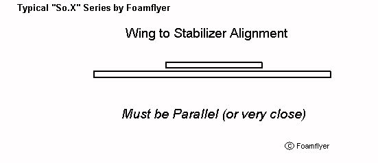
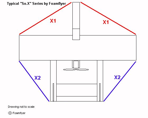
What is "Good Alignment"?
It means nothing is crooked. Take a look at the following drawings. The wing and stabilizer must be parallel to each other (or very close). And looking down at the top of the plane, the wing and stabilizer must also be in alignment to the fuselage. X1 must equal X1, and X2 must equal X2. If it's as much as a 1/4-inch off, don't worry. But the closer it is the better the plane will fly.
Electronics Installation
Cut cavities for the elevator servo and the aileron servo. This can be done with a knife, rotary tool, or soldering iron. It's best to place the servo on the foam, draw around it, then cut the foam out. The servo should fit snugly into the cavity and be flush with the foam. A small strip of packing tape should secure the servos to the foam. Later, getting a servo out is a little tricky, just grab the servo horn and wiggle it until enough of the servo comes out to get a better grip on it.
The receiver should fit into the receiver cavity in the fuselage. Place some tape strips over the receiver cavity to hold the receiver and wires in. It's best to leave the speed control out of the receiver cavity for better cooling airflow.
Attach the motor and prop to the motor mount, and attach the speed control wires to the motor. Remember, this is a pusher so you'll probably have to reverse the wires on the motor. Also, make sure the propeller is attached to the motor in the pushing configuration. The front of the propeller should be towards the front of the plane, and the motor should rotate in the proper direction to direct airflow backwards.
Before installing the battery pack, make the elevator and aileron pushrods.
Pushrods
I usually make pushrods from 3/16-inch hardwood dowel, with a 4-40 threaded stud and clevis at one end and a wire Z-bend at the other. With the servos installed into their cavities, carefully measure from the servo horn to the horn at the control surface. When measuring make sure the elevator and aileron are in the neutral position (a little tape may help hold them in place temporarily). Then make the pushrods to match. It may take some trial and error to get the correct length at first, but it gets easier with practice. Any slight difference in pushrod length can be adjusted at the clevis, and during flight adjusted with the trims on the transmitter.
Here's how I make pushrods.
Balancing and Battery Placement
This step is as critical to get right as making sure all the parts of the plane were in the proper alignment. The battery is placed into a cavity cut into the fuselage so that the plane will balance at the correct point for flight. No lead counterweights should be used to achieve the proper center of gravity, as this will increase the total weight of the plane, which you want to keep as low as possible.
The balance point, or center of gravity for this, and many similar planes, is about 30% of the wing chord measured from the leading edge. So on this plane with a wing chord of 7 inches, the CG should be about 2.1 inches back from the leading edge (7 inches times 30% (or 0.3) = 2.1 inches). Remember, it's better to be a little nose heavy than a little tail heavy.
With both servos, both pushrods, the motor and prop, the receiver and speed control installed in the plane, place a round dowel on a table (I actually use a half-round). Then place the plane on the dowel with the dowel at the correct center of gravity. Place the battery pack on top of the fuselage until the plane balances. Mark the location of the battery pack on the fuselage, then cut the battery pack cavity. Once the cavity is cut, place the battery pack into the cavity (it should fit snugly) and make sure the plane still balances at the proper location. Adjust the battery pack forward or backwards in the fuselage if necessary (it should be right the first time), then you can do a final shaping of the nose of the plane (cutting a little foam off the nose will not change the CG). Remember, a little nose heavy is much better than a little tail heavy.
When the battery pack is in the plane, it should be centered such that cooling air can flow past both sides of the pack. That's why the battery pack cavity should be a slot cut all the way through the fuselage.
Lateral balance can also be checked and adjusted, but should be close already since each servo is about the same distance out from the centerline of the plane.
Finishing
Apply a strip of packing tape to the bottom of the fuselage to act as a landing skid and to protect the foam. If you'll be landing on a rough surface you can use strapping tape instead of packing tape. Also run some tape along both sides of the fuselage to strengthen it.
Repair any large voids or dents in the foam with lightweight spackling. You can also make "putty paint" by mixing lightweight spackling putty in water to a paint-like consistency, then brushing it on the plane. However, this will take longer to dry. When all putty is dry, sand it smooth with fine sandpaper.
After one last blast of compressed air to remove final sanding dust, paint your new foam plane with whatever markings and colors you want. Water-based acrylic craft paint works well and can be brushed on or thinned for an airbrush. Do not use solvent-based spraypaint as it will damage the foam. You could even just use colored Sharpie pens, or colored tape stripes.
It's a good idea to minimize the amount of paint you put on the plane. This will not only save weight, but time also. For example, instead of painting the entire plane, just put some colored highlights, panels, or stripes on it and leave the rest the natural white foam color. Also, avoid painting foam around the servo and receiver cavities, since removing the tape for any reason will also remove the paint from the foam.
Pre-Flight Check
Make sure the elevator and aileron move in both directions, in the correct direction with the transmitter sticks, and do not bind. If binding occurs, just cut or sand a little of the surface away so that there is a small gap between the moving surface and the fixed surface. If the surface moves in the wrong direction with the sticks, just reverse the servo at the transmitter. Also make sure the surfaces are trimmed for neutral. Depending on how well aligned the plane was, it may be necessary to adjust the trims in flight.
Make sure the motor and speed control operate normally, and that the motor spins in the correct direction. Make sure the propeller is firmly attached to the motor with the front of the prop towards the front of the plane.
Check the CG one last time.
Flying
When weather permits, hand-launch the plane by holding it at the bottom near the balance point with one hand, over your head, with the transmitter in your other hand. This can be tricky, but gets easier with practice. You may give the plane full throttle when you throw it, or after it leaves your hand, but in any case don't let the propeller hit your hand. A nice long follow-through throw is good, and I've never had a propeller hit my hand.
Throw the plane forcefully, straight and level, into the wind if there is any. Adjust the trims in flight if necessary. This plane flies well with only one aileron.
Have fun!
Landing
If you wait until the BEC on the speed control activates, you will need to judge your landing approach carefully and conserve or bleed-off energy as with all unpowered planes for a good landing. It's best to land into the wind, if any. When you get good at it you can even do "skid and go's" with a plane like this!
What They're Saying...
Foamflyer,
Finally finished the plane yesterday and put it in the air. All I can say is Thank You! for posting the build information. The plane with a BP21 brushless and 3 cell 2000 mh battery flew beautifully. I could do low speed flybys and then dump the throttle to it and have it over 500� in the air in seconds. The glide rate is fantastic and low speed flight is very stable. You knew all this but I just had to repeat it. I did not spend much time making it look good. But I can do that on the next one.
Thanks again